Upgrade of speaker systems of the world-famous British brand TANNOY
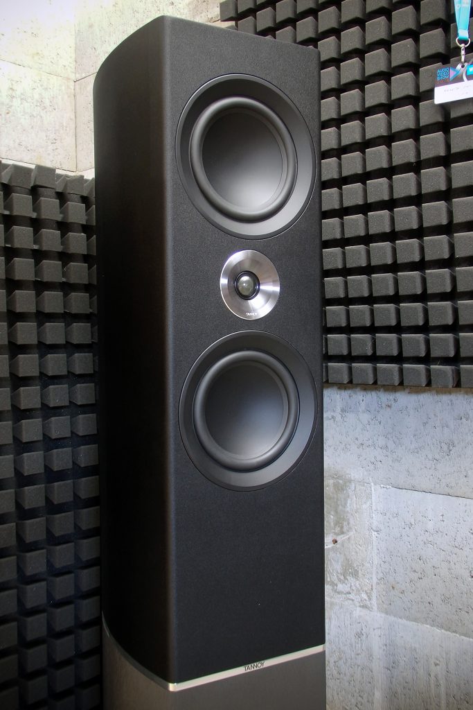

2.5 – way design with a pair of 6.5-inch mid-bass drivers and a tweeter with a small horn. Acoustic design – bass reflex. Composition of the front panel – the tweeter is located between two mid-bass speakers. Visually, it resembles a D`apolito circuit, but in reality it is not, since only the upper driver emits midrange frequencies.
Sound and measurements
According to subjective feelings, the tonal balance has accents on low and high frequencies. Frequency response measurements also show a “U-shaped frequency response”. The increase in the edges of the frequency range relative to the average level is on average +4 dB at low frequencies and +2 dB at high frequencies. The mid-frequency range has a negative slope of -1 -2 dB. The overall uniformity of the frequency range is +/- 4 dB.

Frequency response TANNOY Platinum F6
You may think that I characterize all speaker systems with failed midrange and “U-shaped frequency response”, or something is wrong with my measurements 🙂 Actually my measurements are fine, don’t worry and luckily not all speaker systems are set up this way. They all have a different frequency response. But in fact, in most speakers, you can trace the reduced level of the mid-frequency range against the background of exaggerated bass and high frequencies You can read more about this at this link:
FINE-TUNING OF SPEAKERS

Frequency response of TANNOY Platinum F6 filters
On the transfer functions of the filters, it is possible to trace the characteristic rises of the edges of the frequency range, which coincide with the acoustic measurements of frequency response. That is, we can draw a completely logical conclusion that the frequency response is formed precisely by the appropriate setting of the filters.
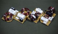
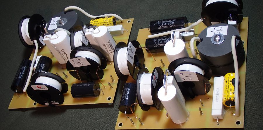
You can also see the strange behavior of the woofer filter characteristics at the lowest frequencies up to 100 Hz. It’s kind of like an impedance curve, isn’t it? I was also a bit confused by it. But when I studied the schematic diagram of the crossover in detail, I saw that in the filter of the mid-bass drivers there is a parallel RC circuit of a 1500 μF electrolytic capacitor and a 10 Ohm resistor connected in series with the drivers. This circuit can be seen on the crossover boards (the big blue capacitors and 10W resistors next to them):

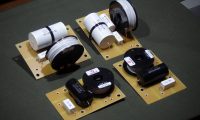
TANNOY Platinum F6 filters
The RC circuit forms a high-pass filter, and in the range up to 100 Hz, its resistance is quite large. For example, at a bass reflex port frequency of 35 Hz, the resistance of the RC circuit is 5 Ohms! Therefore, on the graph of the transfer functions of the filters, we see something similar to the impedance curve. But why is this done? My version: reducing the sound pressure of the bass reflex port, because with the RC circuit off, the sound pressure at the tuning frequency of the port is really too high. I think that the presence of the RC circuit in the filter is a correction of the bass reflex calculation error. Not a very good decision in my opinion.
Two and a half ways
If you consider the filter scheme, it is quite complex.
A pair of mid-bass drivers work in a 2.5-way configuration: both emit low frequencies and one emits mids. That is, when working in such a scheme, the lack of low frequencies of one driver is compensated by another and thus the range is extended towards low frequencies. But what to do when the characteristics of the drivers do not have a lack of low frequencies, that is, they have a uniform frequency response from LF to midrange? It is logical that such a “shortage” will have to be artificially created in the filter scheme. That is, on the graphs of the frequency characteristics of the filters, you can see how the middle frequencies above 150 Hz are filtered from the lower LF driver, the low frequencies below 200 Hz are filtered from the upper part, and then the low frequencies below 100 Hz are additionally cut from both drivers, which is necessary to balance the overall frequency response. But this forces us to create a complex and, in my opinion, unjustified filter scheme.
Which option for creating 2.5-band systems is more optimal and has fewer problems with sound tuning? In my opinion, this is an appropriate selection of mid-bass drivers that do not have a flat frequency response, but with a small positive slope from low to medium frequencies. Don’t worry, this is not a problem – most 5, 6.5 and even 8 inch drivers have this frequency response slope.
To better demonstrate this, I made 2 schematic drawings that illustrate the frequency response behavior of 2.5-way systems with different types of drivers:

Figure 1 
Figure 2
Figure 1 illustrates the frequency response behavior of a 2.5-way speaker system using flat-frequency drivers. In a pair, mid-bass drivers create an increase in the frequency response at low frequencies relative to the middle ones. It is necessary to compensate for this rise in the crossover circuit. This is exactly how it is done in TANNOY Platinum F6.
Figure 2– frequency response behavior of a 2.5-way speaker using mid-bass drivers with a sloped frequency response. Working in pairs, the drivers create a flat frequency response due to their own frequency response characteristics, without additional compensation schemes in the crossover. For example, when creating the RS-II, Center-G, which also have a 2.5-way configuration, I used the positive frequency response slope of the Seas H1456 mid-bass drivers, which allowed to significantly simplify the crossover circuits of these speakers.
Upgrade
My version of the crossovers for these speakers is no less complicated than the factory version, as it also takes into account all the listed features of the design and characteristics of the drivers. But I focused primarily not on sound effects, such as deep bass or high frequency detail, but on the overall evenness of the tonal balance.
Here’s what the measurements look like after the upgrade for comparison:

Frequency response TANNOY Platinum F6 (upgrade) 
transfer functions of filters (upgrade) 
Impedance (upgrade)
The differences between my version of the crossovers and the factory versions:
The signal to the mid-bass drivers does not pass through the RC circuit, which serves to reduce the sound pressure of the bass reflex port. I applied an acoustic resistance panel, which will be mentioned below.
Instead of reducing the level of the signal on the upper woofer, the level reduction is applied on the lower one. Due to which the frequency response of low and medium frequencies is balanced.
The filter of the upper driver has a greater frequency response correction in the range of 500 Hz – 2 kHz, eliminates the dip by 1-2 kHz. That adds more expressiveness to the sound.
The tweeter filter also has frequency response correction and reduces unevenness at high frequencies.
The overall uniformity of the frequency response is included in +/- 2 dB. The minimum impedance is 5 ohms.

Basic and assembly diagrams of filters for upgrade
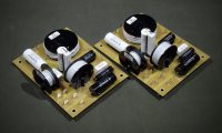
TANNOY Platinum F6 filters (upgrade)
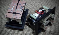
Crossover boards are mounted on the same fasteners as factory crossovers and are connected using standard connectors. I also recommend installing an acoustic resistance panel inside the case between the drivers and the bass reflex port. Such a panel can be made of sheet synthetic foam 1.5-2 cm thick and fixed to the transverse stiffeners that are inside the case.

installation of crossovers 
acoustic resistance panel
You can make crossovers yourself according to the schemes given above.
Or you can order the manufacture of crossovers and you will need to install them and connect them instead of the factory crossovers to your TANNOY Platinum F6.
And also follow the news on our Facebook page: